• Members 545 posts
    Aug. 9, 2024, 9:29 a.m.

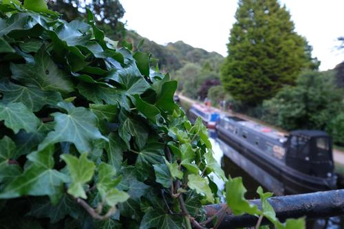
    The size of out-of-focus blur can be measured directly by putting a ruler in the photograph so that it intersects the blur disc produced by a small point of light. The shot below was taken with a 25mm lens at f/1.4. The circular blur disc was from a small bright light over 10 metres away, while the camera was focussed on the ruler that was somewhere around the closest focus for that lens.

    P7303398.JPG

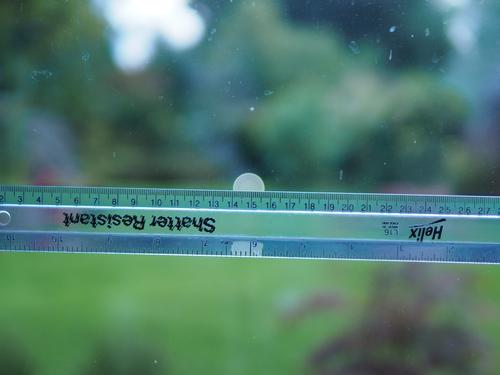
    The scale on the ruler can then be used to measure the diameter of the blur disc in the plane of focus.

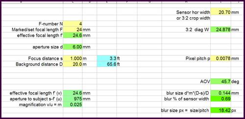
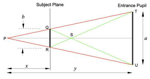
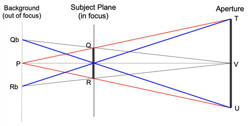
    It is not difficult to calculate the size of the blur disc from a single point of light if the size of the entrance pupil is known, together with the distances of both the ruler and the point of light producing the blur (see this post in an earlier thread).

    Alternative ways of measuring the size of the blur

    The most obvious way is to measure the size of the blur in the image (measured in pixels) and then scale that to the size of the blur on the sensor (measured in mm). The size of the blur on the sensor will differ from the size of the blur in the plane of focus by the image magnification factor (for the plane of focus).

    Merklinger, in his discussions of depth of field, gives a simple formula for the size of the blur in the plane of the object whose image was blurred. I'm not aware of any way this can be measured directly. I think it is probably a purely imaginary concept that is not open to direct measurement. Merklinger imagines how the appearance of the object is changed by being blurred and he imagines how the apparent size of the blurred object would compare to the size of the real object.

    Note: I have started this thread as a result of a discussion in the thread on "Can I calculate focus distance from hyperfocal distance?"

  • Aug. 9, 2024, 3 p.m.

    Why would I need to do this?

    Alan

  • Members 545 posts
    Aug. 9, 2024, 3:14 p.m.

    No more than you need to measure the hyperfocal distance or the depth of field or the size of the diffraction blur.

    In other words, no need at all. This thread is just for those of us interested in the science of these things.

    I thought such topics were allowed in the TQ category? Am I wrong?

  • Aug. 9, 2024, 4:39 p.m.

    Oh yes, they are allowed. I was just curious as to whether I needed to know it.

    Alan

  • Members 129 posts
    Aug. 9, 2024, 5:07 p.m.

    Some people care about size of the blur circles in their backgrounds, i.e. behind the point of focus ... for example, portraits. flowers, landscapes with important foregrounds. Some also care about the blur size of foreground objects under certain circumstances.

    Certain lenses are known for their 'swirly' style of blur e.g. Helios 44 series, 'Petval'. Some find it important how big that blur is.

    You? ... or do you just take what the camera gives you from where you're standing?

  • Aug. 9, 2024, 5:49 p.m.

    I haven't really thought about it. Blur is blur to me.

    USCF0013 (Large).JPG

    Alan

    USCF0013 (Large).JPG

    JPG, 351.4 KB, uploaded by AlanSh on Aug. 9, 2024.

  • Members 129 posts
    Aug. 9, 2024, 5:53 p.m.

    He is a lot more specific than "imagining" here:

    www.trenholm.org/hmmerk/TIAOOFe.pdf see the chapter on convolution.

    From that article, I derived a spreadsheet for blur size at the sensor, FWIW:

    blur on sensor.jpg

    blur on sensor.jpg

    JPG, 368.0 KB, uploaded by TexasTed on Aug. 9, 2024.

  • Members 545 posts
    Aug. 9, 2024, 8 p.m.

    As far as I am aware, Merklinger is completely correct. If you like his method, then go with it!

    Personally, I find the derivation of his various formulae to be unnecessarily complicated. I prefer to keep things simple wherever possible. But these things are often a matter of personal preference.

  • Members 545 posts
    Aug. 10, 2024, 10:52 a.m.

    I do not disagree with anything in that spreadsheet, but my own way of thinking is rather different.

    I would normally start from the field size. For example, suppose I want a field size of, say, 80cm x 60cm, possibly for a head and shoulders portrait. Suppose I am using a 24mm lens at f/4 on a MFT sensor, then the focus distance will be just under 1m and the entrance pupil (aperture) will be 6mm.

    If the background is at 10m, the blur size is 5.40mm (in the plane of focus).
    If the background is at 100m, the blur size is 5.94mm.
    If the background is at 1km, the blur size is 5.99mm.
    For most practical purposes, we can say that the background blur is approximately 6mm if the background is more than 10m away.

    More generally, the background blur is approximately equal to the size of the aperture if the background is more than ten times as far away as the subject.
    There is really no need to work out the precise distances of the subject and background for these cases.

    I normally don't bother to work out the size of the blur on the sensor. I rarely need to.

    For the field size of 80cm x 60cm, the length of the diagonal is 100cm. Hence the blur diameter is 0.6% of the diagonal.

    So, the blur diameter in the image will be 0.6% of the image diagonal, whatever the size of the image and whatever the size of the sensor.

  • Members 129 posts
    Aug. 11, 2024, 1:33 p.m.

    Oh.

  • Members 129 posts
    Aug. 11, 2024, 1:55 p.m.

    Having forgotten long why I produced that spreadsheet, looking again, the term (D-s)/D does indeed limit the blur at the sensor for a given d and m as (D-s) approaches D

    Agreed, provided that "the background blur" is not the size of the blur at the background distance.

    Some folks might find it easier to think of the actual blur size in the object field as being proportional to an angle projected from the point of focus. A "cone of confusion", so to speak, as shown by Lyon's Fig.2 here: kronometric.org/phot/iq/DepthOfField-Lyon.pdf where the angle is (aperture dia. / subject distance) radians.

  • Members 545 posts
    Aug. 11, 2024, 3:43 p.m.

    Some folks might find it easy, but I find it easier to follow the physics and think of the paths of the real light rays that actually create the blur. I can then understand what is happening.

    Those diagrams used by Dick Lyon and Harold Merklinger both show the light rays from a point in the plane of focus. That point is sharp in the image, not blurred. So these light rays play no part in creating the blur. It requires some fairly complicated thinking to use this diagram to work out the blur size.

    The blur is actually produced by a point that is out-of-focus. I prefer to consider the rays from such a point and see more directly exactly how these rays create the blur.

    Screenshot 2023-04-22 at 11.43.42.png

    P is a point of light in the background. It emits light in all directions, but the camera captures only the light that enters the camera lens. So the image is created by the bundle of rays from P within the cone whose apex is the point P and whose base is defined by the entrance pupil of the lens. The cone lies between the ray from P to T and the ray from P to U.

    If the subject plane is the plane of focus, then the ray PT will hit the image at the image of point Q (call it Q'), and the ray PU will hit the image at the image of R (call it R'). Rays from P that lie between PT and PU pass through the subject plane at points between Q and R. These rays will hit the image at points between Q' and R'. Hence light from P will appear in the image as a blur from Q' to R'.

    So, in the subject plane, the light from P appears as a blur extending from Q to R.

    Similarly, if S is a point of light in the foreground, the bundle of rays bounded by the rays ST and SU enter the lens and are used to form the image. These rays appear to come from points between R and Q in the subject plane and hence will appear in the image as a blur extending from Q' to R'.

    It is a matter of simple geometry to work out the size of the blur in the subject plane.

  • Members 129 posts
    Aug. 11, 2024, 6:07 p.m.

    I am confused.

    Is this a rebuttal, or simply a restatement of your view?

  • Members 129 posts
    Aug. 11, 2024, 9:01 p.m.

    I withdraw the statement.

  • Members 545 posts
    Aug. 12, 2024, 2:22 p.m.

    Both Merklinger and Lyon give correct formulae for the out-of-focus blur, but the diagrams they use do not accurately represent the physics. See xpatUSA's posts above for the relevant links.

    I have combined their diagrams and mine to try to see what is going on (I have used the convention that the object is shown on the left and the lens on the right, so that light travels left to right):

    Screenshot 2024-08-12 at 10.13.40.png

    P is the out-of-focus point of light in the background that creates the blur. The red lines are the light rays from P to the top and bottom of the lens aperture. They intersect the plane of focus at Q and R, which defines the size of the blur seen in the plane of focus.

    The angular size of the blur is given by the angle QVR. If the line VQ is extrapolated to meet the background plane at Qb, and line VR is extrapolated to the background plane at Rb, then QbRb gives the apparent size of the blur in the background plane (it subtends the same angle at the point V).

    Now, it just so happens that the blue lines QbU and RbT intersect where the optical axis intersects the plane of focus (subject plane). That can be proved either geometrically or algebraically. However, those blue lines are a purely geometric construct, they do not represent light rays that are responsible for the blur.

    For anyone who is trying to understand the physics, tracing light rays from the point P (red lines) shows how the blur is produced in the plane of focus. Tracing light rays from a point in the plane of focus (blue lines) does not show how the blur is formed.

    Screenshot 2024-08-12 at 10.13.40.png

    PNG, 73.5 KB, uploaded by TomAxford on Aug. 12, 2024.