To be more specific, how is the cross-section of the cone of light at the plane A relevant to the blur produced by a point that is not the apex of the cone?
Aug. 14, 2024
40
-

-

HAND.
-

To whom?!
Interesting statements but somewhat over-simplified, I reckon.
To be far more specific:
"The process by which a sharp image becomes blurred, whether by out-of-focus effects or by motion during the exposure, might be called smearing, filtering or convolution. Convolution is the more general mathematical term, and it might also be used for the de-smearing or sharpening of an image. The arithmetic can get pretty complicated—so we won’t go into that—but it is worth understanding the concept. Understanding convolution might help explain why an out-of-focus image looks as it does.
Convolution is quite simply the process of replacing every small element of one image with another larger image and then adding up the result. If we were to photograph a tiny white speck lying on a black background and if we did not focus accurately, the speck would show up in the image as a small white disk whose diameter is equal to the circle-of-confusion corresponding to the focus error as well as the focal length and diameter of the diaphragm opening of the lens being used. The greater the circle-of-confusion, the larger but dimmer would be the image on the film. If the subject were to consist of not of one, but of two specks, the image would consist of two disks. If the specks were close enough together, the disks would overlap. And where they overlap, the image would be twice as bright. If one of the specks were white but the other gray, one of the disk images would be bright and the other dim."
-
Not at all :)
-

Can not one simply look at the focusing screen at the working aperture and adjust to suit, without all the techno-babble? Seems more practical.
-

For me the explanation and diagram show that points on the focus plane focus to a single point on the sensor. Points behind and in front of the focal plane do not focus to a single point on the sensor hence varying amounts of blur depending on how far a point in the scene is behind or in front of the focus plane.
-
Explanation yes, but diagram is lacking.
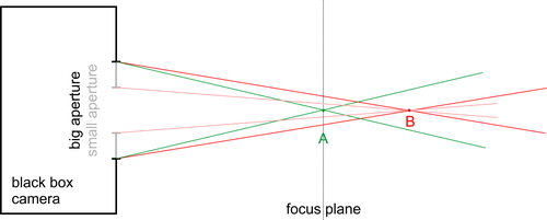
I sketched another diagram, maybe not entirely correct, but more 'bloody obvious' to me - at least when dealing with object side of lens (often blur formation is visualised and calculated at sensor/film side of lens; for me this would be more logical, but there is no actual difference).
Point A is point on focus plane, B at some other distance. There are two possible apertures shown; camera is black box with known property that it records points of focus plane sharply. Rays from point A are drawn in green, rays from point B in red and pink.
Then I claim (based on linear optic principles) that image in camera (sensor) corresponds exactly to object image on focus plane - this is what camera 'sees'.As you can see, for any non-zero aperture diameter point B's image on focus plane is not point, but some 2D image of it (based on geometry it is in shape of aperture, assume it is circle) - (blurred) circle then. Depend on aperture circle diameter is different.
Were point B placed left from focus plane, we could extend rays to focus plane and again got circle, not point. -
Of course it is more obvious to you because you drew the diagram.
Your diagram's intended message might or might not be obvious to everyone else just like Bob's diagram might or might not be clear to everyone else.
-
Yes, precisely, that is the key to understanding object space analysis of ray diagrams.
For any arbitrary ray of light entering the lens, we know exactly where that ray will hit the image. If X is the point at which that ray crosses the plane of focus, then that ray will hit the image at point X', where X' is the image of X.
Of course, this assumes the lens creates a perfect image (i.e. all rays entering the lens from any point X in the plane of focus will converge to a point in the image plane, which we call X').
-

a) There is no lens in the diagram doing any focusing whatsoever.
b) If we assume that the bold lines on the far left represent and aperture then the scale says it is 1m form the sensor, (?).
Personally I have seen much better explanations and diagrams. The main problem I have is why do we need to explain an exact formula to give numbers when to the novice the exact numerical values will be meaningless? Why not just stick to a principals?
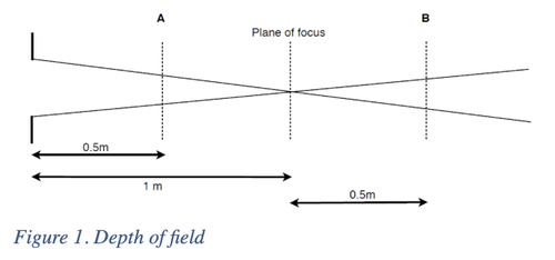
For me it was a diagram like the quick edit (please excuse it) I did below:
-
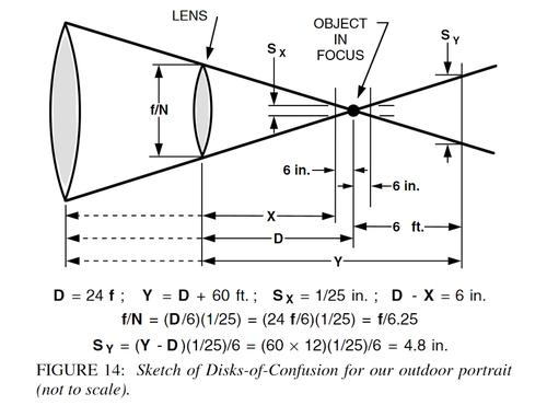
Here's another by Merklinger, this time with example values:
-
Generally yes, but as Bob articles are quite technical, then technical discussion is inevitable :)
-
According to ChatGPT, "Techno-babble" refers to the use of technical jargon, especially in science fiction or technical discussions, that sounds complex and impressive but often lacks real meaning or clarity. It's a mix of scientific or technical terms that may be accurate but are used in a way that doesn't make much sense or serves to obscure the true nature of what's being discussed.
Using that term in this topic is a direct insult to all who have contributed thus far.
-

Only if you give any creedence to ChatGPT...
My definition of techno babble is a bit more expansive than that - to include something that I may not yet understand, or the nitty gritty specs of something I don't need / want to know.
-
Techno-babble can also include concepts/terms people don't know but should know in order to improve their photography.
-
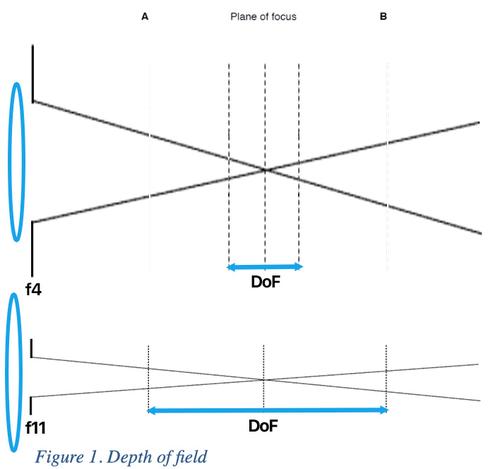
That version is not going to be clear to everyone either.
Your version implies the amount of dof in front of the focus plane will be the same as behind the focus plane which more often than not is not true.
-
HAND.
-
This is where I have the problem.
We are all human, that is we are mostly emotive and illogical by nature, there is no universal scientific truth that when shown suddenly makes the principal clear. In fact the more scientifically acurate and exact you make the diagram the more inacsessable it will be to the general popualtion, and particularly novices. So all diagrams are a simplified representation, and all diagrams are some sort of abstract. The trouble with the Merklinger based diagram is that it's an abstract too far, it requires you to be familiar with the CoC diagram to be able to make any sense of it. There is no camera for the viewer to relate what the viewer is looking at to the reality of a camera and lens they understand. We read left to right, so generally assume that the "rays" are traveling left to right. The diagram most closely relates to the one of rays passing through a lens onto the sensor, and so a lot of readers are going to jump straight to that assumption. The text does nothing to clarify this.
"The rays describe a cone of light based on the aperture with its apex on the focus point."
So focus point is the point the camera is focused on and the cone is a pure abstract meaning "we are only considering those light rays that pass through the aperture on the left (not labeled on the diagram) and so form an imaginary cone. "Oh by the way the light is traveling from the left to the right, but in this case as it's only an abstract diagram to illustrate a mathematical principal it's not really necessary to include any of that." The text then launches into calculating sizes in mm that OOF objects will appear on the sensor, as if that will mean anything to a novice who is probably still thinking of; tree - picture on computer screen without translating that to actual sizes of objects focussed on the sensor and how that relates to the full size image on the computer screen.
"Because the rays travel in straight lines, the shape of cone that the sensor intercepts corresponds to the shape of the image, and its size corresponds to the image of an object the same size as the light cone in front of the lens at point A."
This I find very confusing, a cone is a cone is a cone, it's shape has nort changed.
The trouble with the article is that it is written and proof read by people who are fully conversant with the principals involved, not from the point of view of a novice. What appears obvious is so because it is familiar and understood. You are bringing an understanding to the table that is not being explained in the article and so there is a gap, that stuff you already know, that is missing and prettty much is making the article impenetrable to a pure novice. As a photographer of many years, and not as daft as some, it took me a while to figure out what is missing and make sense of it. And to be honest none of it is any practical use unless you're already conversant and wish a mathematical model to relate to because maths is "your bag".
-
Not all novices are created equal.
In my experience some will be able to understand the article and diagrams and some will struggle with it initially.
-
LOL - If it's useful to anyone, it is not babble, techno or otherwise!
-
So you are now saying there is no techno babble in this thread, according to your definition.
You don't get to decide for other people what is or is not useful to them.
-
Another problem with this diagram (and others showing rays from a point in the plane of focus) is how to illustrate the hyperfocal distance.
Where is the hyperfocal distance in such a diagram?
How does the depth of field behind the plane of focus become infinite (when the plane of focus is beyond the hyperfocal distance)?
-
Just found on one Ilford Photo articles:
Q: What do you call a group of photographers sat around a table talking about depth of field?
A: A circle of confusion.