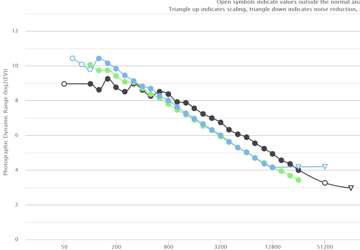
Alan also posted this (note the logarithmic ISO scaling):
June 27, 2025
129
-

-

Don't you have Bob's email? : )
But, sure, I can explain. DR is the ratio of the max signal to the noise floor, usually expressed in terms of stops, over a specified area. Typically, the DR is expressed as a per-pixel measure (which can, of course, be misleading when the pixel counts between the systems being compared are different) and the noise floor is taken to be the electronic noise (often called "read noise"). PTP uses a 20:1 SNR (Signal-to-Noise Ratio) as the noise floor normalized of the size of the CoC (Circle of Confusion) for the sensor (if I remember correctly), which means the "DR" measures will differ from the standard treatment of DR. He also plots against the ISO setting rather than the exposure, which can most definitely result in misleading results when comparing across systems.
OK, all that in place, higher ISO settings typically result in less electronic noise [relative to the signal] than lower ISO settings. For example, if we took two photos of the exact same scene with the same f-number and exposure time, one at ISO 100 and the other at ISO 200, the ISO 200 photo will typically be less noisy than the ISO 100 photo (albeit "overexposed" by a stop if the ISO 100 photo is "correctly exposed"). How much the electronic noise decreases is a function of both the sensor and the ISO setting, and can vary significantly at lower ISO settings, but typically flattens out by ISO 1600 on all sensors (the "flatten out" point is typically referred to as the ISO setting where the sensor becomes "ISO-invariant"). I have examples of this here:
So, let's say a one stop increase in the ISO setting reduces the saturation limit by a stop as well, but also results in one stop less electronic noise. Then the DR would remain the same. However, at some point, the electronic noise will stop decreasing. After that point, the noise floor remains the same, but the saturation limit comes down a stop for each stop increase in the ISO setting, so the DR goes down by a stop as well.
But how would the DR go up when the ISO setting is increased? Simple: the electronic noise decreased by more than a stop. This can absolutely happen with dual gain sensors (usually around ISO 400 or so) and you'll see a little jump at that point, but it can happen at any ISO setting (typically lower ISO settings).
What's important to understand is that DR is the range between the noise floor and saturation limit -- it is NOT a measure of how noisy the photo is, although it is related to the noisiness of the photo. The noise in a photo varies greatly from the dark areas to the light areas. If we had two cameras which were pretty much the same, but one had half the electronic noise as the other but the same saturation limit (and thus one stop greater DR), we wouldn't notice a difference between the photos except in the deepest of shadows, and even then, only if the shadows were heavily pushed so we could see the noise.
So, the whole deal about DR is about the ability to push shadows, keeping in mind, of course, that each stop we raise the ISO setting, we are pushing the entire photo (including the shadows) an extra stop, so differences in DR which might go unnoticed at lower ISO settings (unless heavily pushing shadows) will become more and more apparent at higher ISO settings.
Hopefully, this answers your question and then some!
-
GB - that was fascinating. Two questions:
- What is a "dual gain" sensor?
- Why does higher ISO give less electronic noise? Surely it's the same? Because it's the same electronics.
Alan
-
a transistor has 3 pins base collector emitter, the collector is the input/supply voltage the emitter is the output voltage the base is the controller between the collector and emitter. so if the base is connected to a pixel and collector is supplied with 5 volts or 7 volts with a switch this would be the same as dual gain.
-
There is a technology licensed by Aptina which applies extra capacitance to each photocell requiring more exposure for a given scene, if so applied.
Since ISO(SOS) = 10/(mean exposure) for a mid-gray output, the effective exposure index (ISO number) is reduced when extra capacitance is applied.
-
With dual gain, your analogy requires two transistors, one biased with 5 and the other with 7. Otherwise, using a switch, we would be diving the light captured in some fraction.
-
Alan: this description does not apply in any way to MOS transistors as used in digital image sensors.
-
its a simple example .not getting into OP amps with this simple explaination.
-
a transisitor is a switch period, how hard you turn it on is up to you, same a tap is a tap, dont confuse the simple proceess because its not rocket science that everyone makes out it is.
-
I spent over 20 years as an Electronic Controls design engineer, so your grossly over-simplified statements carry no weight with me and do not help this topic at all.
-
Alan has no idea about electronics and my answer to his question is exactlly how you discribe the "concept"
-
Your answer to his question shows how much you know about semiconductor electronics, to be blunt.
Telling Alan that "a transistor has 3 pins base collector emitter" has absolutely nothing to do with digital image sensor transistors whose connections are called gate drain source and do not operate anywhere near the same as pnp transistors.
-

Whaaaat!?
That answer has nothing at all to do with the question. It would be a classic case of telling someone who simply asked the time, how to build a watch, but it's just a string of gibberish.
There are words there that do mention various parts of a transistor, but it's just a meaningless word salad. Even if understanding transistor function could be an answer, (it's not), it certainly doesn't do any of that.
The best answer as to what is a "dual gain system," in this context is electronic circuitry that applies one level of amplification of the signal at low ISO settings and a higher level of amplification, starting at a higher ISO setting.
Essentially, the lower amplification is applied to all the ISO settings from the lowest up to the second ISO set point, and the higher amplification is applied to all the ISO settings above the upper set point.
As frequently can occur in electronic systems, crossover points are not always without some discontinuities. It's not just the amount of amplification that changes, at the crossover. Different circuitry may be switched in, according to proprietary designs that changes fundamental processing of the signal, enhancing signal quality and other characteristics, that may give the appearance of a slight "improvement" (bump) in parameters.
Since the signal path is a "black box" to everyone but the manufacturer, describing the output to be "higher dynamic range" after the switchover is just speculation. What might be happening is that there is a slight degradation in dynamic range leading into the crossover, which is then corrected by the second stage of processing. The end result is the same.
The point is that there are two distinct stages of signal processing with similar but slightly different measurements. It probably was a design goal that the entire range be a smooth response curve. The discontinuity is an insignificant hiccup.
Rich
-
you need to go back to school
" In simpler terms:
Think of a transistor as a general type of switch, and a MOSFET as a specific, efficient type of switch that's commonly used in modern electronics. " -
brush upon your ignorance, dual gain has nothing to do with iso settings as its added at the analogue stage.
www.electronics-tutorials.ws/io/io_4.html
-
Ok - calm down everyone.
As has been said, I'm not an electronics engineer. But I do understand digital circuitry. Let's move away from the transistors etc.
As I understand it, in order to produce a meaningful picture in low light, the camera has circuitry either on or just after the sensor. This amplifies the signal that the sensor captures. Because of that, more noise is show on the final image. This I understand.
Then you come to 'dual gain' sensors where different circuitry is applied once a certain ISO is reached (which really means once the light recorded drops below a threshhold.). I presume this is done because the original amplification can only go so far before it reaches its ceiling.
Assuming my understanding above is correct, I have two questions:
- Why does the second set cut in so low in the ISO settings (e.g. 200ISO).?
- Why does this appear to produce less noise?
So, can anyone answer those two? Preferably without circuit diagrams.
Alan
-
I found this: Aptina paper on dual-gain sensor (PDF)
It includes circuit diagrams (sorry), where it is clearly seen that they change well capacity, which affects sensor sensitivity before any amplification. As read noise is related to ADC and amplification, then read noise (which is one of noise sources, defining DR) is about the same for low-gain mode and high-gain mode (this is nicely seen in your X-T5 graph).
What happens in Canon, is not that clear - but I suspect there is some similar technology applied. -
it appears to have less noise because you have not changed the exposure. so an image taken at iso 100 is going to be underexposed so when lifted the image has more noise than the properly exposed image at iso 2000 ,the 2000 iso image has activated the dual gain amplifier , its basically turned up the voltage, same happens with microphones that are battery powered or auto gain radios that increase the RF signal before it hits the audio preamp.
forgot to add that more information can be captured/stored in the highlights than the shadows 🤔dont ask me why its just because 😁