• Members 1437 posts
    April 2, 2026, 4:10 p.m.

    Indeed it ain't ... here's an illustration with inner triangles added for two "balanced" settings but something doesn't seem quite right ...

    Exp Tri 2.jpg

    Comments invited ... I really would like to get to the technical basis of the Triangle because it is so easily understood by others and because I still don't quite get it, grump.

    Exp Tri 2.jpg

    JPG, 270.8 KB, uploaded by xpatUSA on April 2, 2026.

  • Members 1798 posts
    April 2, 2026, 11:51 p.m.

    The triangle wasn't meant to be read from as one would read from a graph. It is more an indicator of the relationship between the 3 attributes.

    The plane analogy is interesting... I am struggling to get my head around it. I can get my head around a line in 3D in the positive quadrant, necessarily going through or near to (0, 0, 0)

    Then Brightness can be read directly from the graph as the magnitude of the point for any x, y, z.

  • Members 2648 posts
    April 3, 2026, 8:27 a.m.

    because your lines are OFF 😊try drawing them more accurate.

  • April 3, 2026, 9:13 a.m.

    Being realistic, it's nothing to do with triangles or angles of any sort. It;s just three different parameters that each affect the end result of how exposed the photo is when it is stored on the SD card.

    Alan

  • Members 2648 posts
    April 3, 2026, 10:15 a.m.

    if you draw the lines accurately they will all meet at the centre point of all the triangles.

  • Members 359 posts
    April 3, 2026, 11:04 a.m.

    "Back in the film days," which is a good place to start...

    To produce a consistent "middle grey tone" with a selected film stock then you must ensure that the same density is produced in the film in all situations. So you pointed you meter at your grey card and because it is calibrated for a grey card then it gave you the shutter and aperture settings to achieve that. That's the point of exposure, to make sure that the amount of light hitting the film (per unit area) remains constant in variable lighting conditions, you don't vary the exposure, you keep it constant while the light levels illuminating the subject vary.

    ASA was nothing more than the calibration setting for the light meter and effectively controled the meter's sensitivity.

    ASA was also supposed to be related to film speed where manufacurers would indicate the optimum setting for the camera's meter and an optimum development to go with that. However it turned out that "optimum" had some marketing connotations as well...

    Skip to digital, and the point of exposure is the same, to ensure that a consistent amount of light falls on the sensor for each consistent output level. But the need to match that to a fixed reaction in a film stock is gone. Instead that's replaced with the output jpeg of the camera. So in effect, if you point your camera meter at your grey card then it will show you the aperture/shutter settings needed to reproduce that mid grey tone in the output jpeg for (effectively) whatever light meter calibration you've chosen. It's as good a way as any of thinking about it, you select a meter sensitivity and the camera automatically adjusts the brightness of the output jpeg so your exposure from you gery card reproduces a consitent mid grey tone in the output image.

    Thing with digital though is that you can now work backwards. Instead of choosing a meter sensitivity that matches the film stock then "zero the meter" to indicate the settings required to give the set exposure level for mid grey, you can now choose the preferred settings and then "zero the meter" by changing it's sensitivity, essentiually choosing the amount of processing of the output jpeg calibrated around the brightness of your mid grey card.

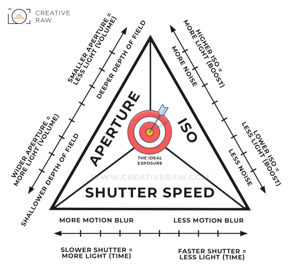
    The "Exposure Triange", to me, seems to be an attempt to produce an elegant and symmetrical overview simply because we desire and elegant and symmetrical overview. It draws connections where no real connections exists, misses the key variable, and seems to miss the key concept of exposure. It also seems to show that we are looking far too much at the camera and the camera alone.

    It doesn't really make much sense.

    For a start we are not trying to make an image lighter, we are trying to keep it consistent. We are trying to ensure that the output tone of our mid grey card photo remains constant in varying light conditions. We change aperture and shutter to ensure exposure remains constant. Exposure is not strictly speaking the aperture and shutter settings themselves, they are just a means of controlling exposure.

    The variable in the equation (that's missing) is the level of illumination or level of light of the scene being photographed. Noise is related to total amount of light that hits the sensor during an exposure and it is far more useful if connected to scene illumination. There is no real direct connection between ISO and noise, ISO only really connects meter reading to output jpeg.

    If you want a diagram then try the dial of a Weston Master V. The lower the number on the inner light dial the more noise you start with. If you press the little button (used to lock ISO setting) so the whole middle spins round and you can select your desired aperture/shutter settings while remembering that spinning clockwise increases noise (effectively reducing shutter for chosen aperture). Then the resultant ISO setting indicated by level of scene illumination combined with your preffered shutter/aperture setting indicates what you should set your ISO dial to to maintain your mid grey card in your output jpeg. It also relates to the brightness of the output raw file, though this is not strictly calibrated and isn't guaranteed.

  • April 3, 2026, 11:57 a.m.

    It is a plane of constant (resulting) brightness, every point coordinates are combination of three values (corresponding to logarithms of S, A and ISO), which give identical result. Intersection of plane and coordinates octant gives us a triangle.
    I marked some point C on the triangle and draw its coordinates x, y, z. These correspond to my previous post variables.

    exp-triangle.jpg

    exp-triangle.jpg

    JPG, 38.6 KB, uploaded by ArvoJ on April 3, 2026.

  • Members 1798 posts
    April 3, 2026, 12:35 p.m.

    Ahhhh, thanks.

    The "constant brightness" was what I was missing. I couldn't see how the plane covered varying lightness. It doesn't. Different lightness, different plane.

    Having said that, my line idea was no better - didn't allow for varying lightness...

  • Members 1437 posts
    April 3, 2026, 3:47 p.m.

    Seeking clarification as to the time factor ... should the octant be made positive somehow (can't have negative brightness and time is fractional so log(t) is negative). On the same basis, what about log(A=f/0.95) = -0.223?

    For example, if log(C) = log(S)+log(A)+log(t) and S=400 and A = f/5.6 and t=1/250, log (t) = -2.398 so not a positive octant ...

  • April 3, 2026, 5:12 p.m.

    Entire idea is not limited to positive octant, it just makes nice triangle there :) Of course plane continues to negative values, logarithms of positive values span range from -∞ to +∞ - no problems with that.
    It is same for your 'normal' exposure triangle - if you choose some parameter outside of range, written there on the sides, then results are also located outside of it.

  • Members 1437 posts
    April 3, 2026, 6:45 p.m.

    Thank you ... busy digesting ...

  • Members 2648 posts
    April 4, 2026, 9:04 a.m.

    you will be a while, as it makes no sense to me to add an oblique projection to the simple 2D equilateral triangle. what value is the cube 🤔

  • Members 1437 posts
    April 4, 2026, 2:02 p.m.

    Miller Indices ... pick one ... 🤔

    Miller_Indices_Cubes2.jpg

    Miller_Indices_Cubes2.jpg

    JPG, 53.5 KB, uploaded by xpatUSA on April 4, 2026.

  • April 4, 2026, 4:04 p.m.

    Just simple aid to draw coordinates of the point.

  • Members 1437 posts
    April 4, 2026, 8:33 p.m.

    For an exposure triangle, is the point C always at the center of the plane as drawn and as is implied here:

    d2u1z1lopyfwlx.cloudfront.net/thumbnails/c428120c-016e-5b42-a266-07ef5adbf956/fd076613-3660-5025-9227-9b30d41ad718.jpg

  • Members 1437 posts
    April 4, 2026, 8:41 p.m.

    No help at all, sorry, and no need to "shout"!

  • April 4, 2026, 8:50 p.m.

    Your image didn't show for me, I attached it:

    fd076613-3660-5025-9227-9b30d41ad718.jpg

    If you are talking about my plane model, then no, entire plane is of constant brightness and we can set point C anywhere - its coordinates (converted to real S/A/ISO values) give always same result. For different brightness you have to shift the plane.

    If you are talking about your linked triangle, then I can't find correct mathematical way to describe relationship of parameters. You can fix one parameter - shutter speed, draw perpendicular (vertical) line from that parameter value, take any point of it, draw two lines, perpendicular to other sides and you get three values, giving you identical result. Unfortunately starting from other sides (A or ISO) does not work this way.

    I would say that your triangle does not give us any mathematically usable basis.

    fd076613-3660-5025-9227-9b30d41ad718.jpg

    JPG, 53.9 KB, uploaded by ArvoJ on April 4, 2026.

  • Members 1437 posts
    April 4, 2026, 9 p.m.

    Thanks - I used HTML

    [img]https://d2u1z1lopyfwlx.cloudfront.net/thumbnails/c428120c-016e-5b42-a266-07ef5adbf956/fd076613-3660-5025-9227-9b30d41ad718.jpg[/img]

    OK and thank you so far for your continuous help!